Site Links
Howdy, Stranger!
It looks like you're new here. If you want to get involved, click one of these buttons!
Quick Links
Categories
In this Discussion
Please review the site Rules, Terms of Service, and Privacy Policy at your convenience. Rules, TOS, Privacy
Get familiar with the reaction system: Introducing the Reaction System
Resistor inductance parallel or in series?
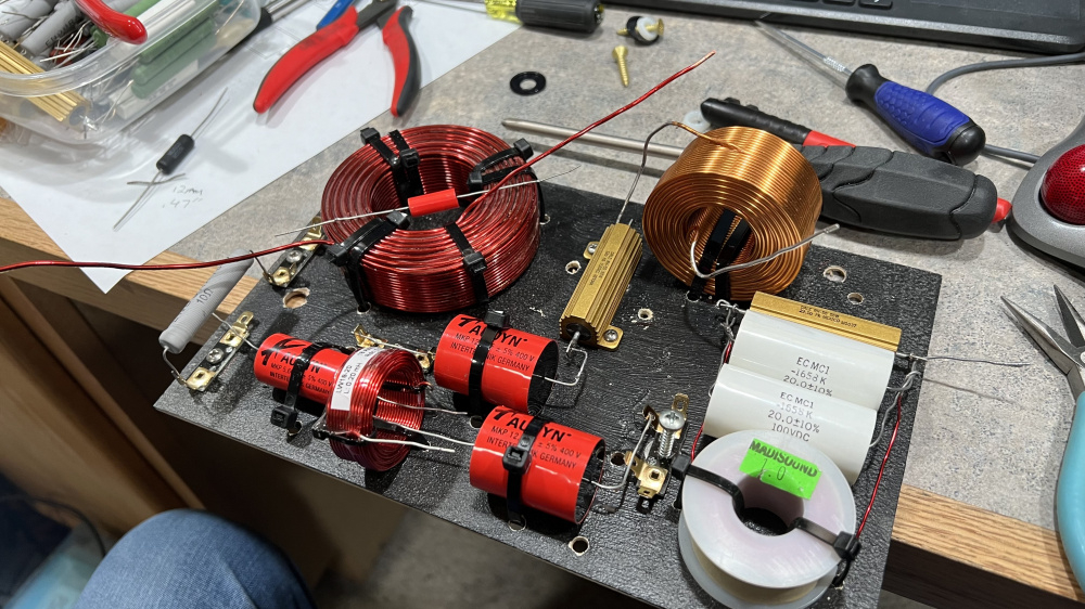
I'm using some surplus Dale aluminum power resistors in my crossovers. I know they have some inductance and my budget LCR meter says it's on the order of 0.11mH. I'm questioning the accuracy of that measurement, but the data sheets are no help on this issue. The question is - when modeling that, would the inductance be in series with the resistor or parallel to it? If it's in series, I'm fine in both instances. If it's in parallel, that will probably be an issue in the damped shunt leg on the LP.


Comments
You would model the stray inductance in series with the resistance. I find it hard to believe that Dale resistor has that high of inductance. I would expect it to be more like an order of magnitude lower, like 11 uH.
Good to know! I think it's probably too low for my meter to read accurately. Even if it really is 0.11mh in series, the difference in the modeled response is on the order of .25dB around the crossover region. I do find it odd that none of the data sheets I pulled from Mouser had any inductance specs. One did say "low inductance" but that was it. Lots of graphs showing thermal performance. I did learn these are good for a continuous long-term 20W without a heatsink, so I should be fine in that regard.
I'm with Craig on this one. I would bet it's even lower than 11uh if it's a small value resistor.
I looked up a Dale data sheet and they make two kinds of resistors. The NH models are non inductive. RH models are their standard model.
Inductance of resistors is inconsequential for crossovers, and typically sand cast wire wound 10W resistor is in the order of 1uH, or 0.001mH.