Site Links
Howdy, Stranger!
It looks like you're new here. If you want to get involved, click one of these buttons!
Quick Links
Categories
Who's Online (5)
- DrewsBrews 4:48AM
- Inertiaman 4:48AM
- rjj45 4:48AM
- Tom_S 4:48AM
- traw 4:48AM
Please review the site Rules, Terms of Service, and Privacy Policy at your convenience. Rules, TOS, Privacy
Get familiar with the reaction system: Introducing the Reaction System
Crossover jig Questions.
I have a decent amount of the CAD work done for the Meniscus crossover jig kit and have even ordered some parts to build a prototype of what i hope will be the final unit.
Currently the design has the ability to "live" switch between 2 different stereo crossovers. The jig uses relays to isolate the two crossovers. This can be run biamped as well as a common input. This same jig can be used to A/B portions of the circuit as well making it so that you can test different capacitors, L-pads, inductors you name it. The Jig will be a 8 1/2 by 11 inch laser etched/cut plywood board that will have all the connections on the top surface.
The switch to control A/B will plug into binding post so that the user can be sitting in the listening position and flip the switch for A/B without changing their listening position (sorry you will have to add your own remote if you want one).
I would love to have some input on what type of connectors that you all would prefer to have on the jig. The original from last years Meniscus event had spring terminals. They were cheep and they filled a need, beyond that they kinda sucked the only advantage that they bring to the table is price at $.50 each. In an effort to make a more user friendly project I would like to consider other options... please post your preference number 1-5 and post any helpful criticisms that you can think of. Thanks.
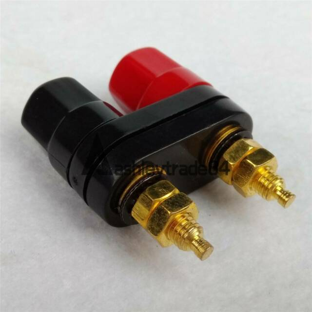
2:
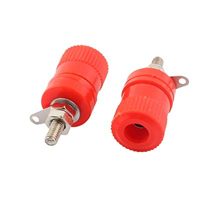
3:
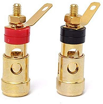
4:
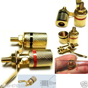
5:
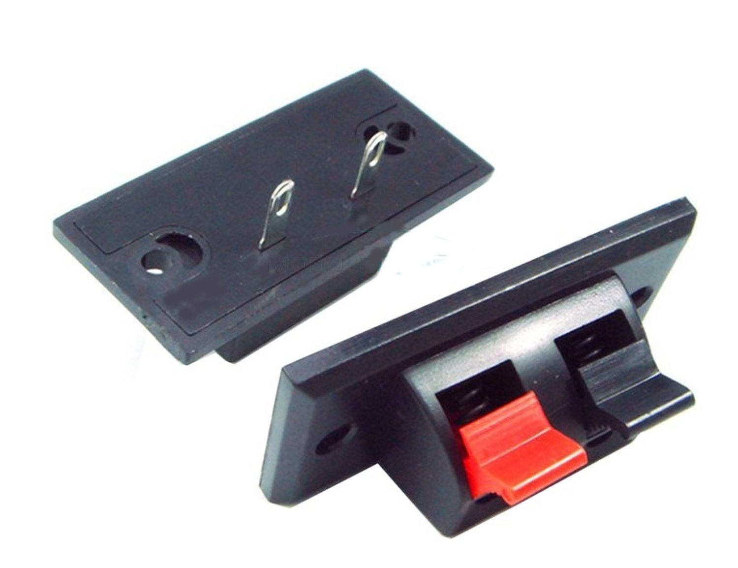
Currently the design has the ability to "live" switch between 2 different stereo crossovers. The jig uses relays to isolate the two crossovers. This can be run biamped as well as a common input. This same jig can be used to A/B portions of the circuit as well making it so that you can test different capacitors, L-pads, inductors you name it. The Jig will be a 8 1/2 by 11 inch laser etched/cut plywood board that will have all the connections on the top surface.
The switch to control A/B will plug into binding post so that the user can be sitting in the listening position and flip the switch for A/B without changing their listening position (sorry you will have to add your own remote if you want one).
I would love to have some input on what type of connectors that you all would prefer to have on the jig. The original from last years Meniscus event had spring terminals. They were cheep and they filled a need, beyond that they kinda sucked the only advantage that they bring to the table is price at $.50 each. In an effort to make a more user friendly project I would like to consider other options... please post your preference number 1-5 and post any helpful criticisms that you can think of. Thanks.

2:

3:

4:

5:

Comments
I like dual banana posts for input from the amp. You can stack dual banana plugs to power additional boards if you are working on a 3 way, for example. For internal connectors, I prefer the spring loaded terminals like #3, but I'm also thinking about using crocodile clips (edit - does not look like anyone carries crocodile clips anymore) - IME, alligator clips are pretty marginal for a crossover board - 2 components are good, but 3 components on a single clip is marginal.
You will also need a lot of jumpers. I ended up making my own with large insulated alligator clips and soldering 18G wires to them. Another question is if you will have ground plane pins on the board. You always need them, but they can limit flexibility.
https://www.amazon.com/WAGO-222-413-LEVER-NUTS-Conductor-Connectors/dp/B000JJPA66/ref=asc_df_B000JJPA66/?tag=hyprod-20&linkCode=df0&hvadid=193984242218&hvpos=1o2&hvnetw=g&hvrand=16593761536469182600&hvpone=&hvptwo=&hvqmt=&hvdev=c&hvdvcmdl=&hvlocint=&hvlocphy=9021890&hvtargid=pla-314836175243&psc=1
I'm still not strong on the Arduino/relay thing yet, though, but A/B switching would be effing awesome.
That said, I vote number 1, but you may also find that the Sure branded 4pc mini-insulated jacks are also cost effective. Those and Neutrik Speakons are what I used on my switcher.
InDIYana Event Website
Thanks for all your hard work on this, Ken. Looks like your project is starting to come together well.
I vote for the #1 dual banana jack for all jig connections. This way, I can quickly connect and disconnect my xovers using cheap dual banana plugs.
I don't like the cheap #5 spring clips at all. Numbers 2,3, and 4 would also be OK, but only if the spacing distance is standardized so that I can use use dual banana plugs on my end.
Bill
Ani,
I only use those Wego nuts for prototyping crossovers and other circuits. I always twist together and solder all electrical connections on final builds.
I acknowledge that amplifiers hate switching the load like this but cannot find a better solution than relays. This will present an immediate disconnection and re-connection to the amplifier. Please make sure that your amplifier is up to the task. Typically class AB would be the best suited to this load type as a class A or D will both have a very negative reaction to this type of switching. Class A and D need a load for output regulation, Some class D amplifiers will have disconnection protection engendered into the design some do not (ask me how I know).
InDIYana Event Website